Simple Automata: Single Input Single Output
An Olin College of Engineering project to design and build a mechanical automaton with a single input and a single, distinct output.
Read the Project Report →The Product Objective
The core challenge was to create a purely mechanical device that translates a single input motion (like turning a crank) into a single, repeatable output motion. The entire machine had to be designed from scratch and fit within a specific size constraint.
One Input
The automaton could only have one point of user interaction to initiate its movement.
One Output
This single input had to translate into one clear, observable output action.
Size Constraint
The entire assembly needed to fit within a 12" x 5" x 12" volume.
The Mechanical Design
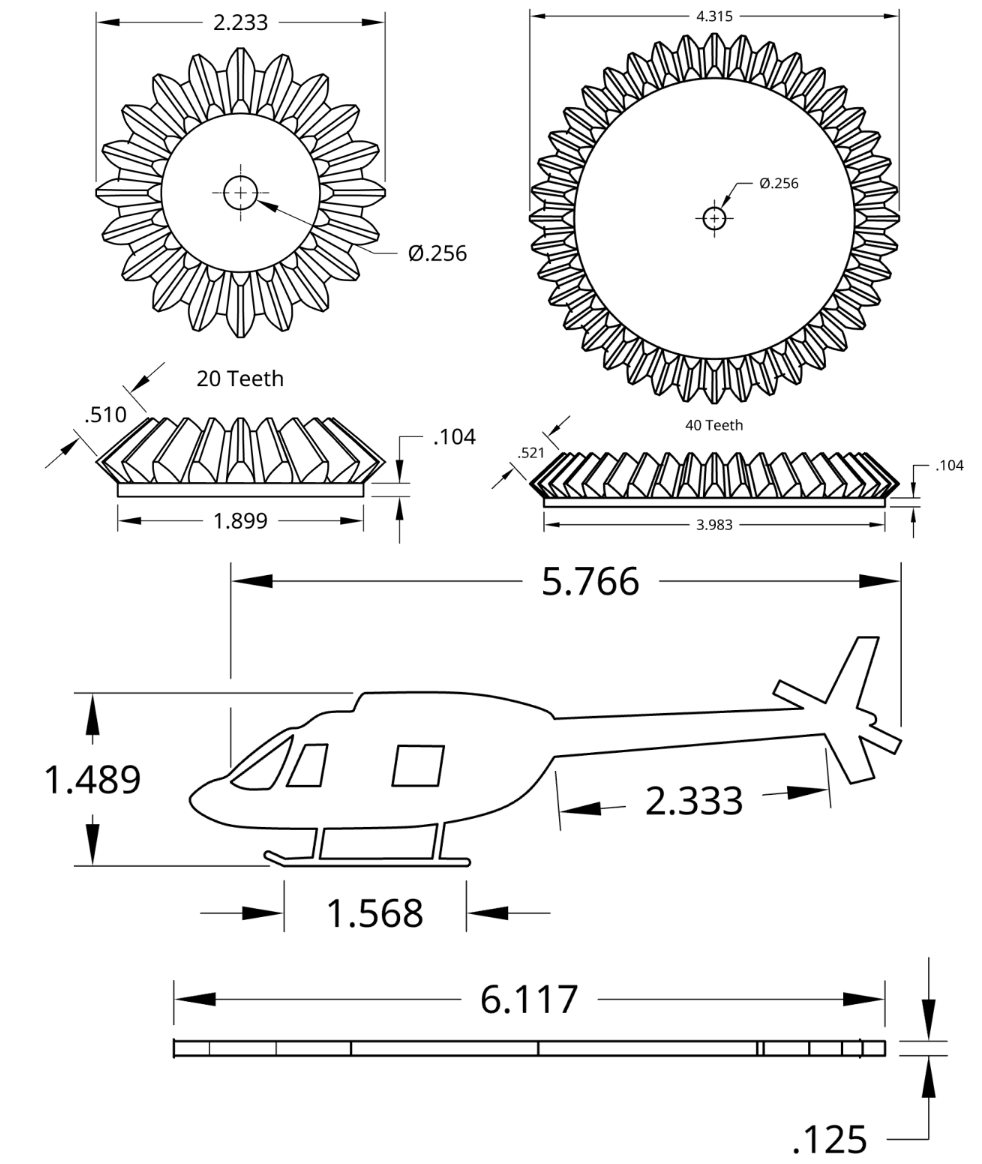
The solution is an automaton that uses a cam and follower mechanism. Turning a hand crank rotates a specially shaped cam, which in turn pushes a follower connected to a linkage. This rotates the propellers of the helicopter.
Key Mechanical Features
-
Cam & Follower System
The core of the machine. The input crank rotates the cam, and the cam's profile dictates the precise motion of the output.
-
Lever and Linkage
A simple lever system translates the vertical motion of the cam follower.
-
Layered Plywood Construction
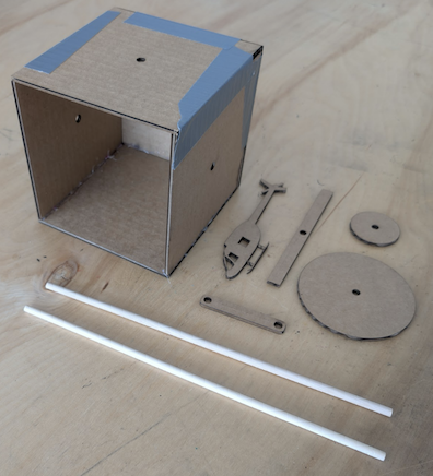
The entire automaton is built from layers of laser-cut plywood, creating a strong, precise, and easily assembled chassis.
-
Designed for Fabrication
All parts were designed in Onshape with laser cutting tolerances in mind, ensuring a perfect fit during assembly.
Learning
The project presented three main challenges. The first was creating a complex helicopter shape in CAD, which was solved by tracing a sketch using the spline tool in Onshape. The second challenge was animating the CAD model for the first time, a problem that was fixed by converting "fastened" mates to "revolute" mates to allow for movement. Finally, a manufacturing issue arose when gluing collars in a tight space, which was overcome by using clamps to hold the parts in place while the glue dried.
Design & Fabrication Process
Brainstorming
Conceptualizing a simple, engaging motion that could be achieved mechanically and had a connection to Olin.
CAD Modeling
Designing every component in Onshape, from the cam and linkages to the chassis, ensuring all parts fit and function together virtually.
Laser Cutting
Exporting the 2D part designs from Onshape and using a laser cutter to precisely fabricate the components from plywood.
Assembly & Testing
Assembling the cut pieces and testing the mechanism to ensure smooth operation and a successful final product.
Tools & Technologies Used
Onshape (CAD)
A cloud-based 3D CAD software was used for the entire design process. This allowed for precise modeling of parts, creating virtual assemblies, and ensuring mechanical feasibility before any material was cut.
Laser Cutting
A laser cutter was the primary fabrication tool. It translated the digital designs from Onshape into physical parts with high precision and speed, enabling rapid prototyping and a clean final build.
Mechanical Principles
The project is a practical application of fundamental mechanical engineering principles, including cam/follower systems, linkages, levers, and kinematic motion, all within a constrained design space.