Kinetic Sculpture: A Symphony in Motion
A fun team project to design and build a kinetic sculpture powered by a belt-driven motor, all fitting within a compact space.
Read the Project Report →The Project Objective
The main goal was to work as a team to create a visually engaging kinetic sculpture. The key constraints were that the motion had to be driven by a single motor via a belt-drive system, and the entire sculpture had to be contained within a 12" x 12" x 5" volume.
Belt-Driven Motion
The sculpture's movement had to originate from a single DC motor and be transmitted via a belt drive.
Complex Movement
The design needed to produce an interesting, multi-layered motion from the single power source.
Compact Design
The entire assembly was required to fit within a strict 12" x 12" x 5" volume.
A Collaborative Creation
Our team's vision was to create a mesmerizing, layered motion using a series of gears. The project became a comprehensive exercise in integrating various manufacturing techniques to bring a dynamic piece of art to life.
It challenged us to blend creative design with precise engineering, managing power transmission, material selection, and assembly within tight constraints.
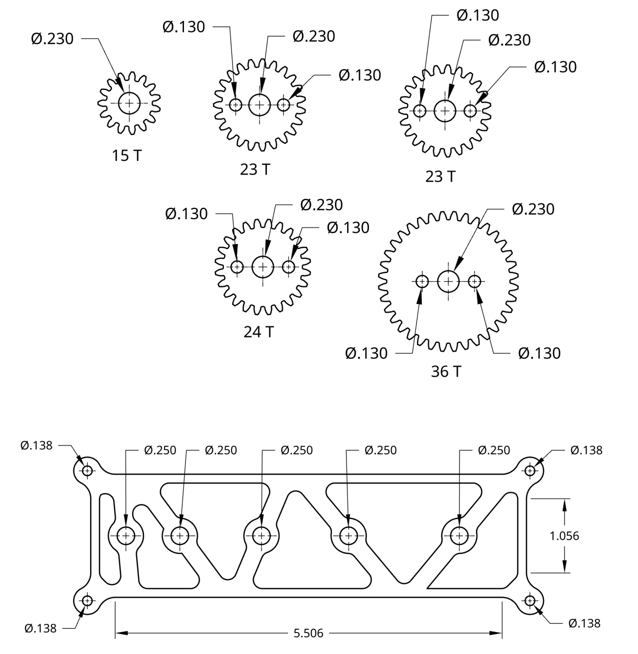
The Mechanical Design
Our design features a large central gear driven by the motor's belt drive. Mounted on this main gear are smaller planetary gears that counter-rotate as the main gear turns. This creates a captivating, multi-layered "gears-within-a-gear" motion.
Key Mechanical Features
-
Belt Drive & Pulleys
A 3D-printed pulley system transmits power from the motor to the main gear assembly efficiently and quietly.
-
Cascading Gear Train
The main gear drives smaller gears, resulting in a complex and visually interesting motion from a single input.
-
Mixed-Material Assembly
The sculpture utilizes laser-cut plywood for the structural frame and gears, with 3D-printed components for pulleys and spacers.
-
Precision Manufacturing
Every part was carefully designed in Onshape and fabricated using tools like the laser cutter, 3D printer, and lathe for a precise fit and smooth operation.
Final Product.
Design & Fabrication Process
Ideation & Sketching
Our team brainstormed various concepts for motion, settling on the cascading gears idea for its visual appeal.
CAD Modeling
We designed the entire assembly in Onshape, simulating the gear interactions and ensuring all parts fit within the size constraints.
Multi-Tool Fabrication
We used a laser cutter for the plywood gears and frame, a 3D printer for the pulleys, and a lathe for custom shafts and spacers.
Assembly & Integration
The final phase involved assembling all components, mounting the motor, and tensioning the belt to bring the sculpture to life.
Tools & Technologies Used
Onshape (CAD)
Used for the complete 3D design, allowing for collaborative work and precise modeling of the intricate gear system.
Laser Cutting
Essential for fabricating the flat components like the main chassis and gears from plywood with high accuracy.
3D Printing
Used to create more complex geometric parts like the motor pulley and spacers, which would be difficult to machine traditionally.
Lathe
A manual lathe was used to create custom-sized shafts and axles, ensuring a perfect fit and smooth rotation for the gears.